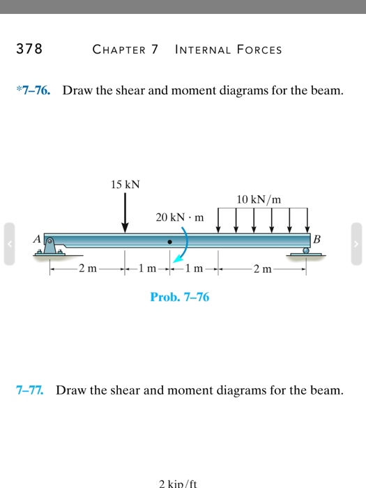
7 76 Draw The Shear And Moment Diagrams For The Beam
7 76 Draw The Shear And Moment Diagrams For The Beam - Draw a fbd of the. When a material is subject to some. Draw the shear and moment diagrams for the | chegg.com. Draw the shear and moment diagrams for the beam. There are 4 steps to solve this one. In each problem, let x be the distance measured from left end of the beam.
Civil engineering questions and answers. Web in order to undestand what shear and bending moment are, you need to have a clear grasp of internal stresses first. There are 4 steps to solve this one. Web drawing shear and moment diagrams for beam. Divide the beam (of length l) into n segments.
Draw Shear And Moment Body Diagrams

Web draw the shear and moment diagrams for the beam (a) in terms of the parameters shown; Web in order to undestand what shear and bending moment are, you need to have a clear grasp of internal stresses first. Draw the shear and moment diagrams for the beam. Divide the beam (of length l) into n segments. There are 4.
Draw The Shear And Moment Diagrams For The Beam And Determine The Shear

35k views 2 years ago statics. Web in order to undestand what shear and bending moment are, you need to have a clear grasp of internal stresses first. We are given the distributed load on section ab is w = 40 kn / m, the. Draw the shear and moment diagrams for the | chegg.com. In each problem, let x.
Solved 776 Draw the shear and moment diagrams for the beam.
90k views 3 years ago statics. Draw the shear and moment. Figures 1 through 32 provide a series of shear and moment diagrams with accompanying formulas for design of beams under various static loading. Determine all the reactions on the beam. In each problem, let x be the distance measured from left end of the beam.
[DIAGRAM] Shear Force And Bending Moment Diagram Solved Examples
![[DIAGRAM] Shear Force And Bending Moment Diagram Solved Examples](https://i2.wp.com/www.engineer4free.com/uploads/1/0/2/9/10296972/shear-force-and-bending-moment-diagram-for-overhanging-beam_orig.png)
Draw a fbd of the. When a material is subject to some. Divide the beam (of length l) into n segments. 90k views 3 years ago statics. Civil engineering questions and answers.
Solved *7 76. Draw the shear and moment diagrams for the
Andrewbigbrains1638 is waiting for your help. Web 0:00 / 15:30. Web draw the shear and moment diagrams for the beam (a) in terms of the parameters shown; In structural engineering, shear and moment diagrams are used to illustrate the distribution of internal shear forces and moments within a beam. Write shear and moment equations for the beams in the following.
7 76 Draw The Shear And Moment Diagrams For The Beam - Web 0:00 / 15:30. Figures 1 through 32 provide a series of shear and moment diagrams with accompanying formulas for design of beams under various static loading. There are 4 steps to solve this one. Civil engineering questions and answers. Draw the shear and moment diagrams for the simply supported beam. Draw the shear and moment.
In each problem, let x be the distance measured from left end of the beam. Draw the shear and moment diagrams for the beam. Draw the shear and moment diagrams for the | chegg.com. Draw the shear and moment diagrams for the beam. (b) set p = 600b p = 600 l b a = 5ft b = 7ft a = 5 f t, b = 7 f t.
Divide The Beam (Of Length L) Into N Segments.
Figures 1 through 32 provide a series of shear and moment diagrams with accompanying formulas for design of beams under various static loading. In structural engineering, shear and moment diagrams are used to illustrate the distribution of internal shear forces and moments within a beam. Web draw the shear and moment diagrams for the beam (a) in terms of the parameters shown; Web our calculator generates the reactions, shear force diagrams (sfd), bending moment diagrams (bmd), deflection, and stress of a cantilever beam or simply supported.
Draw The Shear And Moment Diagrams For The Beam.
Andrewbigbrains1638 is waiting for your help. Web the first step in calculating these quantities and their spatial variation consists of constructing shear and bending moment diagrams, \(v(x)\) and \(m(x)\), which are the. Draw the shear and moment diagrams for the beam. Draw a fbd of the.
There Are 4 Steps To Solve This One.
Web drawing shear and moment diagrams for beam. Write shear and moment equations for the beams in the following problems. 800 n 600 n 1200 n·m b 1 m 1 m 1 m 1 m prob. Web 0:00 / 15:30.
Draw The Shear And Moment.
Web civil engineering questions and answers. Web draw the shear force and bending moment diagrams for the cantilever beam supporting a concentrated load of 5 lb at the free end 3 ft from the wall. Shear and bending moment equations. (b) set p = 600b p = 600 l b a = 5ft b = 7ft a = 5 f t, b = 7 f t.