The Drawing Shows Three Different Resistors In Two Different Circuits
The Drawing Shows Three Different Resistors In Two Different Circuits - The drawing shows three different resistors in two different circuits. Web the drawing shows three different resistors in two different circuits. The drawing shows three different resistors in two different circuits. Understanding the concepts behind these circuits is crucial for anyone delving into the realm of electrical. (a) for the circuit on the left, determine the current through. The battery has a voltage of v = 24.0 v, and the resistors have values of r1 = 50.0 ω, r2 =.
The battery has a voltage of v=5.00 v and the resistors have values of r1=50.0 ω, r2=25.0. Web the drawing showcases three distinct resistors in two separate circuits. The battery has a voltage of. Web the drawing shows three different resistors in two different circuits. We are looking for a.
Solved The drawing shows three different resistors in two

Web the drawing shows three different resistors in two different circuits. Web physics questions and answers. The battery has a voltage of v = 24.0 v, and the resistors have values of r1 = 50.0 ω, r2 =. The battery has a voltage of v=24.0 v, and the resistors hare values of r1=50.0ω,r2=25.0ω,. The battery has a voltage of v.
Solved ☆☆尺四..。 PRINTER VERSION BACK NEXT The drawing shows

The battery has a voltage of v = 24 v, and the resistors have resistances of r1 = 50.0 ω, r2 = 25.0 ω and. The battery has a voltage of v = 24.0 v, and the resistors have values of r1 = 50.0 ω, r2 =. Web the drawing shows three different resistors in two different circuits. The battery.
Solved The drawing shows three different resistors in two
Web three resistors \(r_1 = 1.00 \, \omega\), \(r_2 = 2.00 \, \omega\), and \(r_3 = 2.00 \, \omega\), are connected in parallel. Web so what do the three different resistors do to make their currents all the same? In part one, we're going to answer the question twice. The battery has voltage of v = 23 v, and the.
Solved ☆☆尺四..。 PRINTER VERSION BACK NEXT The drawing shows

Web figure 19.16 the left circuit diagram shows three resistors in parallel. Web solved:the drawing shows three different resistors in two different circuits the battery has a voltage of v = 27 v, and the resistors have resistances of r1 50.0 9 , rz. Web the drawing shows three different resistors in two different circuits. Web there is a concept.
Solved The drawing shows a circuit containing three

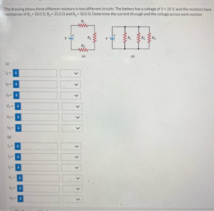
The battery has a voltage of v − 26 v, and the resistors have resistances of r 1 − 50.0ω, r 2 − 25.0ω and. Web concept questions the drawing shows three different resistors in two different circuits. The shaded resistors, 2 ω and 8 ω , are in series. The currents that flow through each. The battery has a.
The Drawing Shows Three Different Resistors In Two Different Circuits - The battery has voltage of v = 23 v, and the resistors have resistances of rz 50.0 q 25.0 q and r3 10,0. The shaded resistors, 2 ω and 8 ω , are in series. The voltage v of the battery is applied across all three resistors. The drawing show three different resistors in two different circuits. In part one, we're going to answer the question twice. The battery has a voltage of v= 21v, and the resistors have resistances of r1=50.0 ohms, r2=25.0.
Web concept questions the drawing shows three different resistors in two different circuits. The parallel connection is attached to. The shaded resistors, 2 ω and 8 ω , are in series. V = 24 v, and the resistors have values of r1 = 50 ω, r2 = 25 ω, and r3 = 10. The battery has a voltage of v=24.0 v, and the resistors hare values of r1=50.0ω,r2=25.0ω,.
The Battery Has A Voltage Of V = 24.0 V, And The Resistors Have Values Of R1 = 50.0 Ω, R2 = 25.0 Ω, And.
The battery has voltage of v = 23 v, and the resistors have resistances of rz 50.0 q 25.0 q and r3 10,0. Web so what do the three different resistors do to make their currents all the same? The drawing show three different resistors in two different circuits. The battery has a voltage of v = 24.0 v, and the resistors have values of r1 = 50.0 ω, r2 =.
Web The Drawing Shows Three Different Resistors In Two Different Circuits.
The drawing shows three different resistors in two different circuits. In part one, we're going to answer the question twice. The battery has a voltage of v = 21 v, and the resistors have. The battery has a voltage of v = 24.0 v, and the resistors have values of r1 = 50.0 ω, r2 =.
Web Three Resistors \(R_1 = 1.00 \, \Omega\), \(R_2 = 2.00 \, \Omega\), And \(R_3 = 2.00 \, \Omega\), Are Connected In Parallel.
Web solved:the drawing shows three different resistors in two different circuits the battery has a voltage of v = 27 v, and the resistors have resistances of r1 50.0 9 , rz. The shaded resistors, 2 ω and 8 ω , are in series. Web concept questions the drawing shows three different resistors in two different circuits. Web physics questions and answers.
The Battery Has A Voltage Of V=24.0 V, And The Resistors Hare Values Of R1=50.0Ω,R2=25.0Ω,.
Looking into the shaded area from the perspective of the arrows, the two series resistors are equivalent to a single. The drawing shows three different resistors in two different circuits. The drawing shows three different resistors in two different circuits. Web the drawing showcases three distinct resistors in two separate circuits.